Nacrtak Earthwork traditionally represents the most important value part within the development of low-volume forest roads. Accurate estimates of earthwork quantity are imperative to forecast development bills and give a boost to the monetary manage of street development operations. Traditionally, earth-work volumes are estimated employing strategies that think of floor statistics obtained from survey stations alongside street grade lines. However, these strategies could not present actual estimates when terrain variations between survey stations are ignored. In this study, we developed a computerized mannequin to precisely estimate earthwork volumes for the proposed forest roads through the use of a high-resolution digital elevation mannequin .
We utilized our mannequin to 3 hypothetical forest street layouts with totally different floor slopes and terrain ruggedness conditions. We examined the consequences of varied cross-section spacings on the accuracy of earthwork quantity estimation assuming that 1-meter spacing gives the »true« earthwork volume. We additionally in contrast our mannequin consequences with these obtained from the normal end-area method. The consequences point out that as cross-section spacing will raise the accuracy of earthwork quantity estimation decreases caused by lack of the power to seize terrain varia-tions. We quantified earthwork differences, which multiplied with terrain ruggedness rang-ing from 2 to 21%.
As expected, brief cross-section spacing ought to be utilized to enhance accuracy in earthwork quantity estimation when roads are deliberate and positioned on hilly and rugged terrain. Prediction of roadway is among the primary helpful components on fill and minimize slope volume, rate and disturbance in forest street constructions. The goal of this research was to develop fashions for prediction of forest roadway applying synthetic neural community and a number of linear regression . For this purpose, 192 cross profiles have been measured on the Soordar-Vatashan forest roads. Within every sample, hillside gradient, slope direction, rock share ratio and texture of soil have been recorded because the inputs and roadway was recorded because the output.
According to coefficient of willpower , a number of correlation coefficient and root imply sq. error and % error, the ANN was extra victorious than regression mannequin in prediction of roadway. P PAN/Adds a parameter with grips to a dynamic block definition. PA PASTESPEC/Pastes objects from the Clipboard into the present drawing and controls the format of the data. PAR PARAMETERS/Controls the associative parameters utilized within the drawing.
PARAM BPARAMETER/Adds a parameter with grips to a dynamic block definition. PC PCINWIZARD /Displays a wizard to import PCP and PC2 configuration file plot settings into the Model or existing layout. PE PEDIT/Edits polylines, objects to be joined to polylines and associated objects. PON SHOWPALETTES/Restores the screen of hidden palettes. PRINT PLOT/Plots a drawing to a plotter, printer or file. PS PSPACE/Switches from a mannequin area viewport to paper space.
PU PURGE/Removes unused items, resembling block definitions and layers, from the drawing. QP QUICKPROPERTIES/Displays open drawings and layouts in a drawing in preview images. QVD QVDRAWING/Displays open drawings and layouts in a drawing utilizing preview images. QVDC QVDRAWINGCLOSE/Closes preview pictures of open drawings and layouts in a drawing. QVL QVLAYOUT/Displays preview pictures of mannequin area and layouts in a drawing.
QVLC QVLAYOUTCLOSE/Closes preview pictures of mannequin vicinity and layouts within the present drawing. RE REGEN/Regenerates the full drawing from the present viewport. REA REGENALL/Regenerates the drawing and refreshes all viewports. REG REGION/Converts an object that encloses an vicinity right into a vicinity object. REN RENAME/Changes the names assigned to gadgets akin to layers and dimension styles.
REV REVDATE /Inserts or updates a block containing username, existing time and date and drawing name. M MOVE/Moves objects a specified distance in a specified direction. MA MATCHPROP/Applies the properties of a specific object to different objects. ME MEASURE/Creates level objects or blocks at measured intervals alongside the size or perimeter of an object. MEA MEASUREGEOM/Measures the distance, radius, angle, enviornment and quantity of chosen objects or sequence of points. MLA MLEADERALIGN/Aligns and areas chosen multileader objects.
MLC MLEADERCOLLECT/Organises chosen multileaders that comprise blocks into rows or columns and shows the end result with a single leader. MLE MLEADEREDIT/Adds chief strains to or removes chief strains from, a multileader object. MLS MLEADERSTYLE/Creates and modifies multileader styles. MS MSPACE/Switches from paper area to a mannequin area viewport.
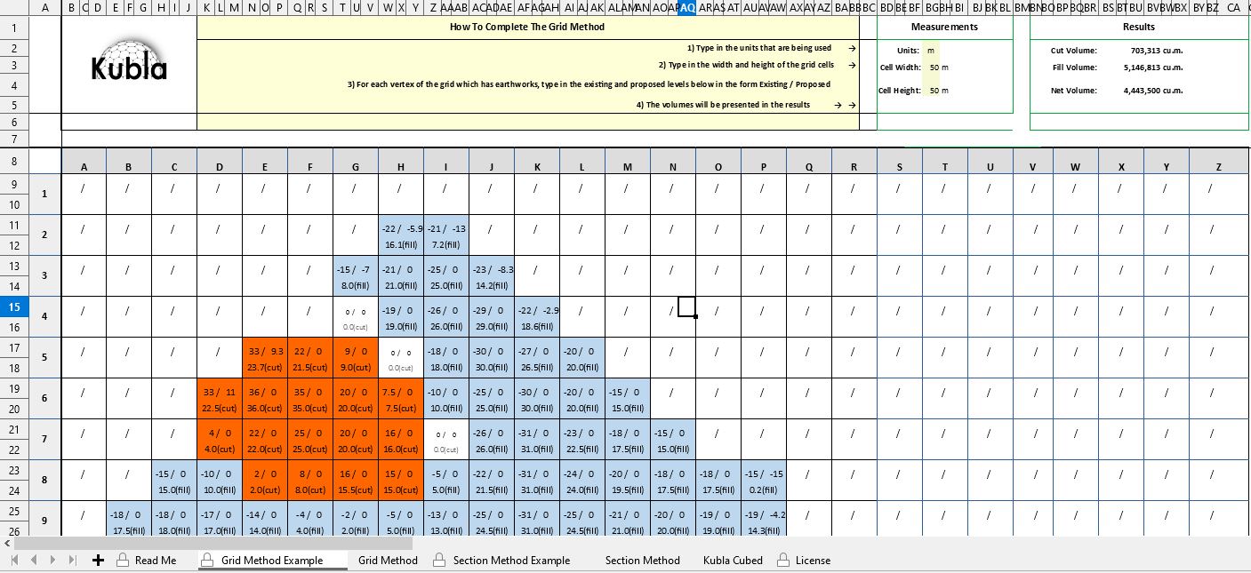
NORTH GEOGRAPHICLOCATION/Specifies the geographic location details for a drawing file. O OFFSET/Creates concentric circles, parallel strains and parallel curves. The grid approach to calculation includes drawing a grid onto the plan for the earthwork project.
For every node of the grid, decide the prevailing and proposed floor degree and calculate the minimize or fill required. Once the minimize or fill depth is calculated, multiply the worth by the world of the grid cell. Do this for every sq. of the grid, then add the volumes collectively to work out the overall minimize and fill volumes for the project. Following a bug reported by a user, I even have up to date my Dynamic Block Counter program to Version 1.1. Following worthy consumer feedback, I even have up to date my Layer Prefix/Suffixapplication which enables a consumer to use a prefix or suffix to the layer names of all layers present in a selection.
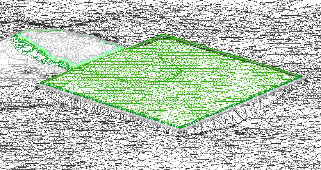
The up to date code fixes a bug whereby the prefix and/or suffix was being utilized & eliminated quite a few occasions equal to the variety of objects within the selection. The up to date code additionally removes the restriction current within the earlier variation which prevented layers whose layer identify started out or ended with the identical character because the prefix or suffix from being chosen for processing. Finally, the brand new edition offers extra verbose output to point to the consumer precisely which layers have been renamed by the program. My Add Objects to Block program has been up to date to Version 1.2. The Triangulated Irregular Network and Digital Terrain Model Methods.The Triangulated Irregular Network approach makes use of documents created by AutoCAD (".tin" files) on topographic surfaces to work out volumes. This, in turn, permits for the creation of quite actual Digital Terrain Models.
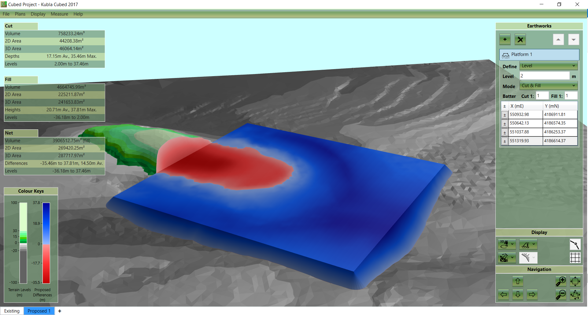
Given the large variety of calculations required, that is usually a course of that may solely be finished on a computer. The DTMs enable for direct calculation between a floor and a hard and fast elevation or two such surfaces. DTMs may even be generated for various soil strata in an excavation, permitting for direct calculation of volumes for every soil type. So how do estimators calculate the quantity between two surfaces? This is usually an incredibly tricky course of because the quantity that the elevation of the soil floor adjustments can range significantly and irregularly throughout the site.
The first floor is usually the prevailing web web web web website topography, at the same time the second reveals the post-construction web web web web website grades. Post development grades may outcome from excavation of present soil, by the location of further soil, or by some blend of the two. The volumes required to put soil are traditionally designated as constructive quantity at the same time these volumes ensuing from excavation are handled as destructive volumes. The resultant numbers could very properly be added collectively to get a cut-to-fill stability for the site. A well-designed web web web web website will finish in a balanced minimize to fill with the online quantity of the 2 equaling zero. Depending on the character of the location and its proposed earthwork, there are a quantity of alternatives attainable for precisely estimating the ensuing earthwork volumes.
The grid way includes drawing a uniform grid onto a plan of the earthworks project, and taking off the prevailing and proposed floor degrees at every node of the grid. With these values the typical depth of minimize or fill required on every cell of the grid is calculated, and the quantity for every cell is obtained by multiplying the depth by the cell area. By including the volumes for every cell jointly the whole minimize and fill volumes for the undertaking would be estimated. I even have up to date my Extract Nested Block program to Version 1.1. The up to date variation incorporates further error trapping to ban number of blocks nested inside dynamic blocks or xrefs , and nested blocks residing on locked layers.
The program may additionally now ignore non-uniformly-scaled block references . S STRETCH/Stretches objects crossed by a variety window or polygon. TC SCALE/Enlarges or reduces chosen objects, holding the proportions of the item the identical after scaling.
SCR SCRIPT/Executes a sequence of instructions from a script file. SET SETVAR/Lists or variations the values of system variables. SN SNAP/Restricts cursor motion to specified intervals.
SO SOLID/Creates solid-filled triangles and quadrilaterals. SPL SPLINE/Creates a clean curve that passes as a result of or close to specified points. SU SUBTRACT/Creates a brand new area by subtracting one overlapping area from another. TA TEXTALIGN/Aligns a number of textual content objects vertically, horizontally or obliquely TB TABLE/Creates an empty desk object. TEDIT TEXTEDIT/Edits a dimensional constraint, dimension or textual content object. TH THICKNESS/Sets the default 3D thickness property when creating 2D geometric objects.
TI TILEMODE/Controls whether or not paper area might possibly be accessed. TOL TOLERANCE/Creates geometric tolerances contained in a function manage frame. TR TRIM/Trims objects to satisfy the sides of different objects.
ST TABLESTYLE/Creates, modifies or specifies desk styles. UN UNITS/Controls co-ordinate and angle show codecs and precision. UNHIDE UNISOLATEOBJECTS/Displays UNISOLATE objects within the past hidden with the ISOLATEOBJECTS or HIDEOBJECTS command. Z ZOOM/Increases or decreases the magnification of the view within the present viewport. W WBLOCK/Writes objects or a block to a brand new drawing file.
X EXPLODE/Breaks a compound object into its element objects. V VIEW/Saves and restores named views, digital camera views, structure views and preset views. G GROUP/Creates and manages saved units of objects referred to as groups.
B BLOCK/Creates a block definition from chosen objects. H HATCH/Fills an enclosed region or chosen objects with a hatch pattern, reliable fill or gradient fill. J JOIN/Joins related objects to kind a single, unbroken object.
I INSERT/Inserts a block or drawing into the present drawing. In this paper, an optimization program developed to supply an optimum vertical freeway profile for a preselected horizontal alignment is described. The purpose of this system was to offer native freeway engineers and planners in Singapore with a realistic assist for freeway geometric design and site analysis.
A dynamic programming formulation was adopted to attenuate the general cost, which incorporates earthwork, land acquisition, materials, and automobile working costs. A real-life numerical instance is introduced for instance program application. Selecting an optimum vertical alignment when satisfying reliable practices and design constraints is a vital process for the period of street construction.
The quantity of earthwork operations will rely on the design of the vertical alignment, so a very good vertical alignment can have a profound affect on last development costs. In this research, we toughen the efficiency of a past mixed-integer linear programming model, and we suggest a brand new quasi-network circulation model. Both fashions use a piecewise quadratic curve to compute the minimal expense vertical alignment and take earthwork operations into account. The fashions reflect on a number of functions similar to side-slopes, and bodily blocks within the terrain. In addition to enhancing the precision, we suggest a number of procedures that velocity up the seek for a solution, in order that it's feasible to make interactive design tools.
How To Calculate Cut And Fill Volume In Autocad We report numerical exams that validate the accuracy of the models, and cut down the calculation time. With CadTools you can actually create your personal floor versions primarily based on objects within the drawing or import triangles from DWG . You can create profiles and cross-sections of a number of surfaces, calculate volumes and plot contours. In these programs, appreciable error can show up on the boundaries counting on the extent of the topo coverage.
The packages convert the topo into TINS as half fo the 3d model. You even must use break strains to accomodate walls, curbs, etc. The packages permit you to make use of the composite, pyramid or grid strategies for the earhtwork calcs counting on the kind of calculations. My Copy to Layouts program has now been fully rewritten and up to date to Version 1.1.
The program permits a consumer to repeat a number of objects to all or chosen format tabs in a drawing; this up to date model is extra strong with cleaner code for improved readability. Following worthwhile suggestions acquired from a number of users, my Nested Move program has now been up to date to Version 1.1. The new edition makes it possible for the consumer to pick out a number of nested objects to be moved, with choice highlighting to offer visible suggestions for the chosen objects. The new edition will even transfer solely the 'outermost' nested object when the consumer has chosen an object nested a number of degrees deep - this additionally resolves a problem through which the consumer might transfer nested dimension components.
The accompanying animated demonstration has additionally been up to date to mirror the brand new functionality. I even have up to date my Strikethrough Text software to Version 1.2. GD GRADIENT/Fills an enclosed region or chosen objects with a gradient fill. GEO GEOGRAPHICLOCATION/Specifies the geographic location data for a drawing file. HI HIDE/Regenerates a 3D wireframe mannequin with hidden strains suppressed. ID ID/Displays the UCS co-ordinate values of a specified location.
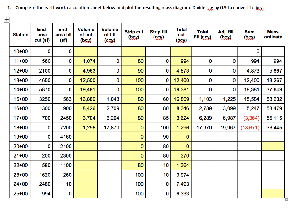
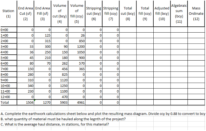
IMP IMPORT/Imports recordsdata of various codecs into the present drawing. IN INTERSECT/Creates a 2D location object from the overlapping location of two or extra present regions. The cross part process includes plotting cross sections of the prevailing and proposed stages at common intervals throughout the mission site. For every of the cross sections, the reduce location and the fill location is determined. The quantity between every pair of sections is estimated by multiplying the typical reduce or fill location of the 2 sections by the space between them. Once these volumes have been calculated for every pair of sections the full reduce and fill volumes are obtained by including all of them together.


